Direct answer
Carry one coordinated site-interface file from the unit manufacturer to the civil, structural, geotechnical, accessibility and construction teams. It should identify support reactions and anchoring information, site soil evidence, foundation geometry, finished-floor elevation, drainage, deck and stair loads, door conditions and the continuous route from an arrival point to the guest room.
A platform at Glamping Show Americas is display support. It is not evidence that the same foundation, deck or accessible route works on a property.
Below the unit
Start with controlled unit and soil information.
Ask the supplier for the current model and revision, support locations, reactions or design loads, allowable tolerances, anchoring concept, connection details and limits on foundation type. A generic footprint is not a foundation package.
The USDA Natural Resources Conservation Service describes Web Soil Survey as a planning source. Its engineering manual also makes the boundary clear: engineering structures may require site-specific investigation and testing. Use mapped soil data to ask better questions, not to select a footing or declare bearing capacity.
Record who commissions geotechnical work, who designs the supports and who checks compatibility with the unit. Include fill, frost, groundwater, slope, erosion and buried work when relevant. The responsible professional decides the investigation and criteria.
Name the inspection or survey record required before delivery. This connects to the delivery and set handoff, where foundation acceptance belongs before a truck and set crew are committed.
Finished floor
Set the elevation with grading and drainage.
Finished-floor elevation changes grading, water movement, step count, ramp length, deck height, guards, utility risers and the distance from delivery surface to bearing points. Do not let the unit elevation and civil grading plan evolve in separate files.
Draw a section from the arrival area through the path, deck or landing and into the room. Mark grades, drainage, finished floor, door sill, landings and utility crossings. A plan view can hide the vertical problem; the section exposes it.
Resolve roof, deck and site drainage before decorating the edge. Later soil placement can change water movement and step geometry. Landscaping, paths and snow storage need space without burying clearances or directing water toward the unit.
Keep classification separate from physical design. The foundation-versus-chassis guide compares development pathways. This file coordinates the selected unit and site; it does not decide classification or approval.
Deck interface
Treat the deck as a structural and operating package.
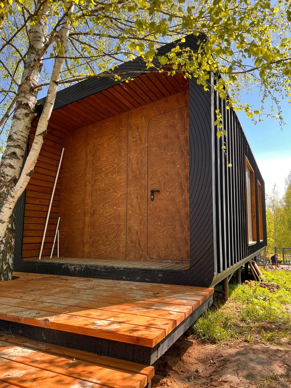
A deck may carry guests, furniture, snow, stairs, a ramp or lift, guards, screens and concentrated loads at an entry. It may conceal utility connections or block service access. That makes it technical scope, not a finish added after delivery.
Record the door swing, threshold, landing, wall clearances, attachment restrictions and waterproofing boundary. If the deck is independent, show the gap and movement detail. If it attaches, the supplier and responsible designer need to approve the connection.
Separate shipped work from field work. Stairs, guards, handrails, skirting, ramps, lifts and lighting may appear together in a rendering but sit in different contracts. The quote normalization guide keeps those packages visible.
Show how technicians reach shutoffs, panels, HVAC equipment, plumbing connections and the underside. A perimeter treatment that must be dismantled for routine service is an operating cost disguised as architecture.
Accessible route
Draw a continuous path from arrival to room.
The 2010 ADA Standards require accessible routes to connect applicable site arrival points, accessible facilities, elements and spaces. Chapter 224 addresses transient lodging guest rooms; Chapters 3, 4 and 8 provide related scoping and technical provisions. The project team must determine the federal, state and local requirements governing the property.
Start at parking, passenger loading, a public way or another applicable arrival point. Continue across the surface, changes in level, slopes, ramps or lifts, landings, door maneuvering space and threshold. Then check the path inside the room. A compliant-looking ramp attached to an isolated deck does not establish a continuous route.
U.S. Access Board guidance says accessible floor and ground surfaces must be firm, stable and slip resistant. Ask who specifies the surface, controls cross slope and drainage, and maintains it after weather and use.
Do not use an “ADA option” label as the evidence file. Request the exact model plan, entry detail, room features and assumptions. Confirm guest-room count, dispersion, routes and amenities with the design team and authority having jurisdiction.
Role matrix
Give every interface an owner and release point.
Use four columns: input, responsible party, controlled document and release point. Include unit supports and anchoring, soil investigation, foundation design and verification, grading and finished floor, deck and entry work, accessible route, utilities, service access and pre-delivery acceptance.
Use names, not “by others.” If parties share a boundary, state which drawing controls and who resolves conflicts. Date every document. A revised footprint can invalidate foundation, deck and route work even when the marketing name stays the same.
At the show, ask the supplier to mark support points, entry datum, lifting restrictions and field-installed items on the current drawing. Request the digital file afterward, then compare it with the site section and responsibility matrix. A documented limitation can be a useful answer because the team can respond before money is committed.
FAQ
Foundations, decks and route questions
Can the display platform be used as a foundation detail?
No. It supports a temporary display in a controlled venue. The project foundation depends on the selected model, site conditions, design criteria, approvals and responsible professionals.
Is a soil survey enough to design a foundation?
Not by itself. NRCS soil mapping is useful for early screening, but site-specific investigation and testing may be needed for engineering design.
Should the cabin supplier design the deck?
Only if the contract includes that work and identifies the responsible designer. Otherwise, the supplier should provide controlled unit-interface information for the project deck designer.
Does an accessible unit create an accessible guest route?
No. The route has to connect the applicable arrival point, site elements, entrance and required room features under the standards governing the property.
When should foundations and decks be released for construction?
After unit identity, site investigation, grading, finished-floor elevation, route, utility crossings and design responsibilities are coordinated to the level required by the project team and authorities.
Sources
Sources
- Glamping Show Americas: official 2026 structure list
- Glamping Show Americas: official floor plan and exhibitor list
- USDA NRCS Web Soil Survey
- USDA NRCS National Engineering Manual
- U.S. Access Board: 2010 ADA Standards, Chapter 2
- U.S. Access Board: 2010 ADA Standards, Chapter 4
- U.S. Access Board: 2010 ADA Standards, Chapter 8
- U.S. Access Board: guide to accessible routes
- U.S. Department of Justice: 2010 ADA Standards
Sources checked September 27, 2026. Event facts may change; the organizer's live pages control. This independent guide is not affiliated with or endorsed by the event or cited authorities. It does not determine classification, accessibility scope, soil capacity, foundation type, structural loads, drainage or deck design, permit approval, product suitability, price or schedule.
Next step
Bring one property and one candidate model.
Use the calculator to expose missing site, access, climate, utility and operating inputs before releasing design or requesting a complete quote. It does not calculate foundation cost, soil capacity, structural loads, accessible-route compliance, approval, revenue or occupancy.
Open the project calculator